Dear Friends,
Here is another technical issue that our Client faced during operation, and a solution provided by AMS:
Technical Analysis: Mechanical Failure and Re-engineering of Remote-Controlled Butterfly Valve Actuation Interfaces
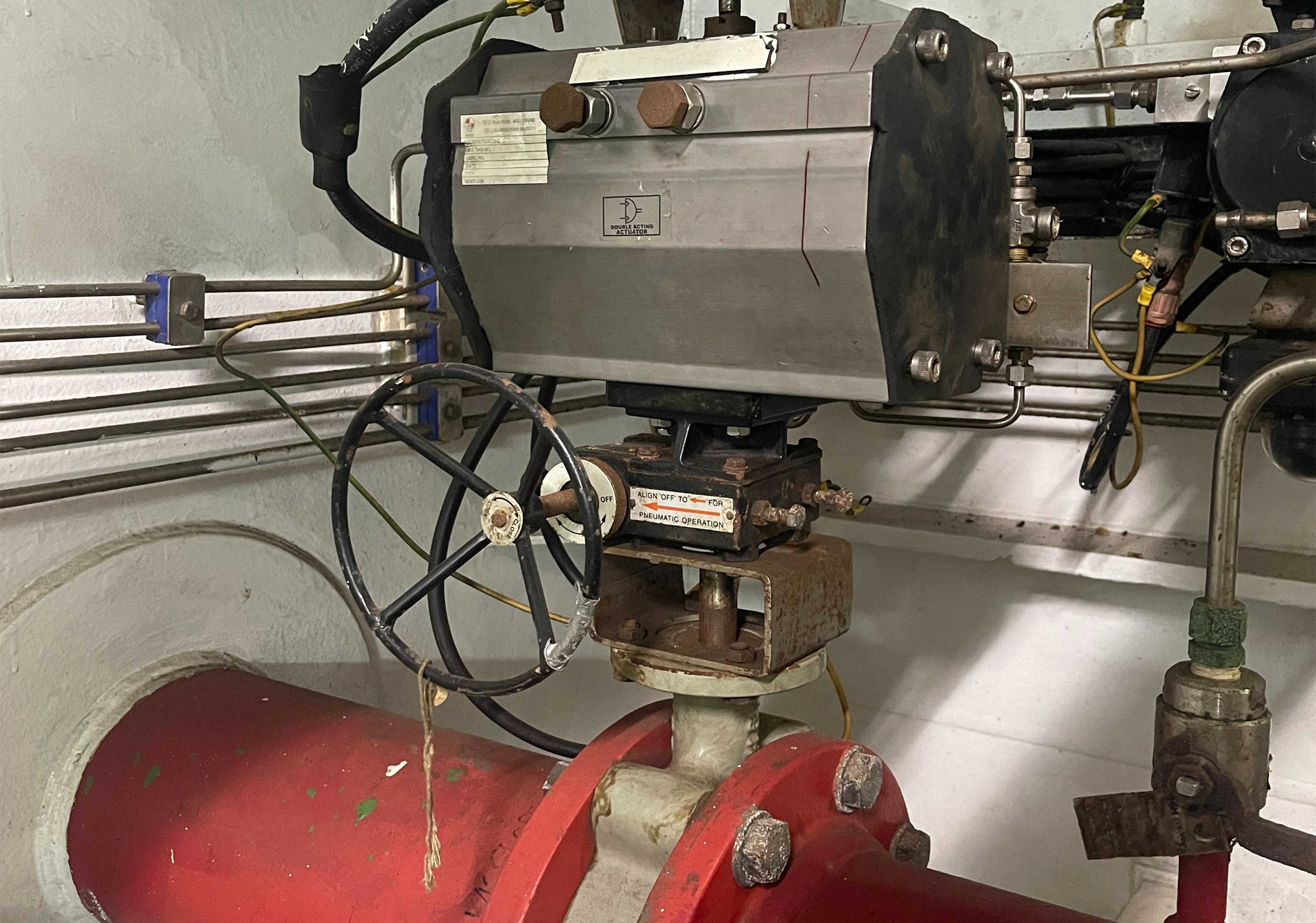
- Asset Under Analysis: Remote-controlled butterfly valves equipped with pneumatic actuators and manual override gearboxes.
- Asset Operational Lifespan: ~15 years.
1. Root Cause and Cascade Failure Analysis
The operational failure is cumulative, driven by the interaction between severe elastomer degradation within the valve body and an inherent engineering flaw in the actuator-to-valve mounting interface.
When discussing the "hardening" or "stiffening" (embrittlement / loss of elasticity) of EPDM in seawater, the physical and chemical processes are fundamentally different from those of NBR. EPDM does not "dry out" in water because it contains virtually no plasticizers to be leached. Instead, its hardening is the direct result of chemical aging of the polymer network itself.
A. The Physico-Chemical Mechanism of EPDM Hardening
- Over-Crosslinking (Polymer Degradation): Continuous exposure to dissolved oxygen in seawater, combined with thermal stress, triggers ongoing chemical reactions within EPDM. New, unintended chemical bonds form between the polymer chains. The molecules become locked tightly together, causing the rubber to lose its ability to stretch and flex. It turns rigid.
- High Compression Set (Loss of Elastic Memory): Hardened EPDM loses its "memory." If the butterfly valve stays closed for a long time, the rubber deforms under the pressure of the disc. Once hardened, it remains permanently compressed and fails to spring back to its original shape when the valve is opened.
- Calcification and Salt Embedding ("Cementing"): Under pipeline pressure, seawater forces its way into the microscopic pores of the EPDM. Over time, salts (calcium, magnesium, sulfates) crystallize inside the rubber matrix. These micro-crystals act as a rigid filler, literally turning a flexible rubber sleeve into a stiff, plastic-like composite.
B. Physical and Visual Signs of Hardened EPDM
Inspecting an EPDM valve liner that has reached its theoretical age limit (over 10–12 years) or has been exposed to accelerated aging reveals:
- Extreme Shore Hardness Increase: A new EPDM liner typically measures around 65–70 Shore A. Fully hardened EPDM can spike to 85–90 Shore A (feeling like a rigid plastic jug). It becomes impossible to indent it with a fingernail or a screwdriver tip; the tool will simply slide off.
- Brittle Edges: If you attempt to flex or bend the sealing lip of the sleeve, it will not deform elastically. Instead, it will crack, chip, or crumble like a dry biscuit.
- Glazed or Glossy Surface: The originally matte rubber surface takes on a shiny, "glazed" appearance, often covered with microscopic cracks visible under magnification.
- Failure of Manual Override Components: A key physical diagnostic marker discovered during the asset audit was a widespread pattern of broken manual worm gearboxes installed between the valves and actuators. When the internal EPDM hardens completely, the mechanical resistance becomes so immense that attempts by the crew to manually force the valve open or closed using wheels or levers result in the catastrophic shearing of internal worm gears long before the rubber yields.
C. Consequences of Static "Closed" Hardening on Valve Operation
Once the EPDM liner hardens in the closed state, the valve fails mechanically in three distinct ways:
- Internal Leakage: Because the rubber is rigid, the metal disc can no longer compress the seating surface to create a drop-tight seal. Seawater easily passes through the microscopic gaps.
- Spike in Operating Torque: Hardened rubber offers massive resistance. The torque required to rotate the disc into the seat increases exponentially.
- Mechanical Tearing: If force is applied to close the valve completely, the sharp edge of the metal disc will shear, gouge, or tear chunks out of the brittle EPDM rather than sealing against it.
D. The Static "Fully Open" Failure Scenario
When a butterfly valve with an EPDM liner is left in the fully open position for a long period, the hardening process occurs while the rubber is in its uncompressed, relaxed state. If an attempt is made to close the valve after years of static open operation, a severe mechanical failure occurs step-by-step:
- The "Zero Elasticity" Collision: In a healthy valve, closing the disk relies on an interference fit—the metal disk is slightly larger than the inner diameter of the rubber sleeve, compressing the rubber to create a seal. When the EPDM has hardened into a rigid state while open, it loses its ability to yield. Instead of a smooth squeeze, the metal disk hits a solid, unyielding wall of hardened rubber.
- High Torque Spike and Component Failure: Because the rubber will not compress, the seating torque skyrockets. A human operator attempting manual closure will quickly strip or shatter the teeth of the worm override gearbox. For automated systems, the pneumatic actuator will draw maximum stall torque, eventually shearing the drive interface completely off if limits fail.
- Destruction of the EPDM Liner (Gouging and Tearing): If the driving force is powerful enough to force the disk into the seat anyway, the brittle EPDM cracks and shears. The sharp edge of the bronze or stainless steel disk acts like a knife, gouging, slicing, and tearing large chunks of EPDM out of the seating area. The localized impact can break the vulcanized bond, causing the rubber sleeve to detach from the metal body entirely.
- Severe Catastrophic Leakage: Once the disk is forced closed through the shattered EPDM, the valve leaks worse than before. The torn and missing chunks of rubber leave wide, permanent pathways for seawater to bypass the disk, rendering the valve incapable of achieving a drop-tight seal.
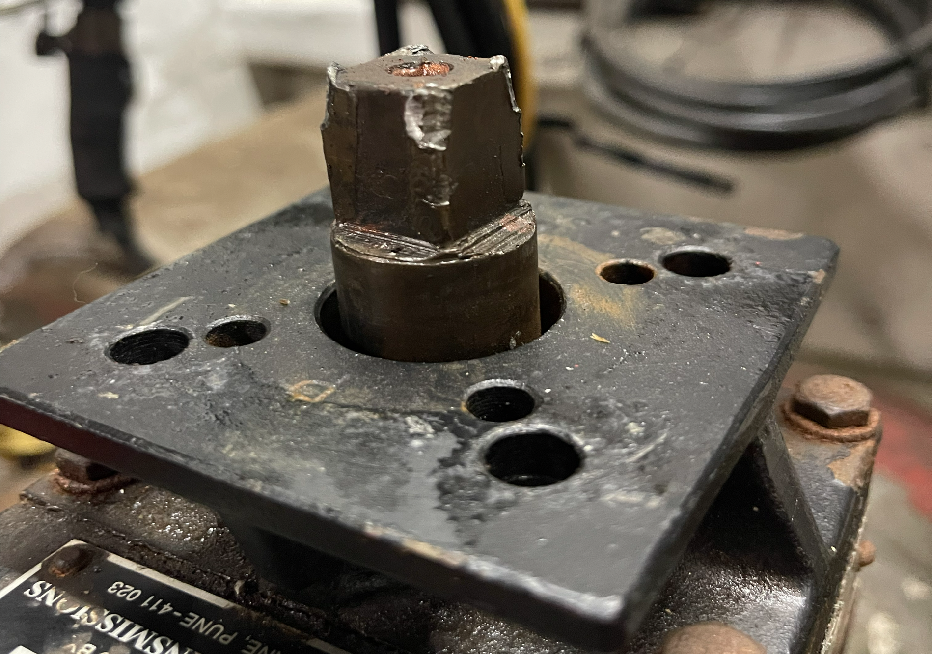
This picture clearly highlights an OEM design flaw: an insufficient adapter length that allows only partial engagement with the internal valve adapter.
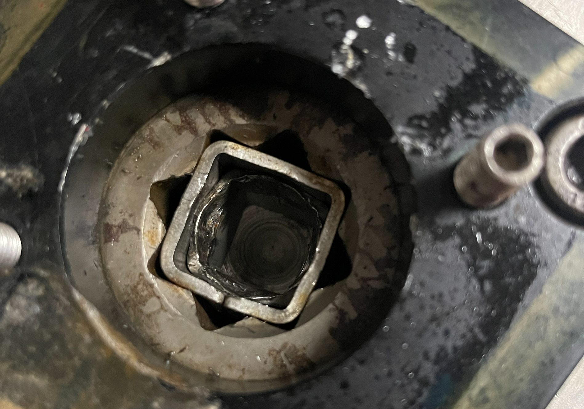
This clearly illustrates why cutting corners with cheap solutions doesn’t pay off. Combining two adapters in one assembly without a matching installation height always leads to hidden costs down the road.
2. The Systemic Industry Challenge: ISO 5211 Deviations and Custom Adaptors
A primary engineering challenge during the refit of legacy vessel systems is the non-compliance of valve manufacturers with international standards, which severely complicates straightforward asset replacement:
- Non-Standard Valve Top Flanges: Manufacturers frequently deviate from the standardized dimensions for mounting flanges and Pitch Circle Diameters (PCD) specified in ISO 5211.
- Custom Drive Tolerances: Deviations from standard drive stem dimensions create significant mechanical backlash or completely prevent standard couplings from fitting.
- Mechanical Play and Feedback Alignment Failure: Even a minor dimensional discrepancy creates excessive clearance. This makes it mathematically impossible to precisely calibrate the actuator's rotation angle and the position feedback system. For a butterfly valve, this lack of precision prevents the disk from reaching its absolute 100% sealing position, leading to continuous bypass leakage.
- Shipyard Workarounds and Interchangeability Failures: Due to these manufacturing tolerances, shipyards are forced to fabricate bespoke, custom adaptors tailored exclusively to a specific batch of non-standard valves during initial vessel construction. When a shipowner attempts to replace a worn-out legacy valve with a new unit, the original custom adaptor fails to fit the new stem due to minor yet critical dimensional discrepancies.
3. Interface Design Flaw and Mechanical Shearing
The entire output torque of the actuator was concentrated on the adaptor connecting the pneumatic drive to the butterfly valve stem. This coupling assembly suffered from a critical design flaw from day one:
- Insufficient Engagement Depth (Short Stem): The factory-installed adaptor was engineered too short. The drive stem engaged with the internal reduction sleeve (27x17 mm adaptor) only partially—occupying less than 50% of the total available socket depth.
- Stress Concentration: Because of this shallow engagement, the substantial rotational force generated by the actuator was focused onto a minimal surface area of the driving faces.
- Metal Stripping ("Rounding Off"): When the valve disk seized due to the hardened EPDM (either locked closed or colliding during a forced closure), the pneumatic actuator continued to exert its maximum stall torque. Compounded by the reduced contact area and existing tolerances from non-standard sizing, the localized stress exceeded the yield strength of the material. This resulted in the total shearing and rounding off of the driving flats on both the adaptor stem and the internal star coupling of the actuator, rendering the remote control system completely inoperable.
4. Applied Engineering Solution and Pre-Installation Re-Engineering
While our company provided detailed technical consultations and procurement guidelines to the shipowner, the replacement valves delivered on-site by the owner's supply chain still deviated from the original required dimensions. Furthermore, since the newly selected replacement pneumatic actuators are currently in transit and yet to be delivered to the vessel, our team carried out a rapid, proactive re-engineering and CNC fabrication package based on technical specifications and manufacturer drawings to ensure zero downtime upon their arrival:
- Component Audit & Validation: Conducted a comprehensive technical evaluation of the owner-supplied hardware, which featured a robust Double-D (DD) drive stem configuration but arrived with non-standard mounting flanges and non-matching Pitch Circle Diameters (PCD).
- Bespoke CNC Conversion Frame Fabrication: To resolve the physical mismatch between the new valves and the vessel's original installation footprint, standard off-the-shelf components were unusable. We engineered and CNC-machined custom intermediate conversion frames (adapter plates/brackets) designed to bridge the geometric gap and mount perfectly to the custom valve tops.
- CNC Machining of Extended Drive Adaptors: Working directly from the official manufacturing drawings of the received valve batch and the technical specifications of the incoming actuators, we CNC-machined a complete set of custom drive adaptors. Based on precise calculations of the total interface assembly length, these units match the exact geometric profile of the new Double-D stems, completely eliminating mechanical backlash while ensuring 100% full engagement depth inside the newly sourced 27x17 mm internal reduction sleeves.
- Technical Parameter Pre-Alignment & Validation: Cross-verified all upcoming integration parameters on paper and through precision machining. This included calculating optimal torque output allowances, verifying the physical footprint profiles, and preparing the connection mappings for the pneumatic solenoids and digital position feedback limit-switch heads. This comprehensive engineering groundwork ensures that as soon as the new actuators arrive on-site, the entire assembly can be mated instantly with zero play and absolute alignment.
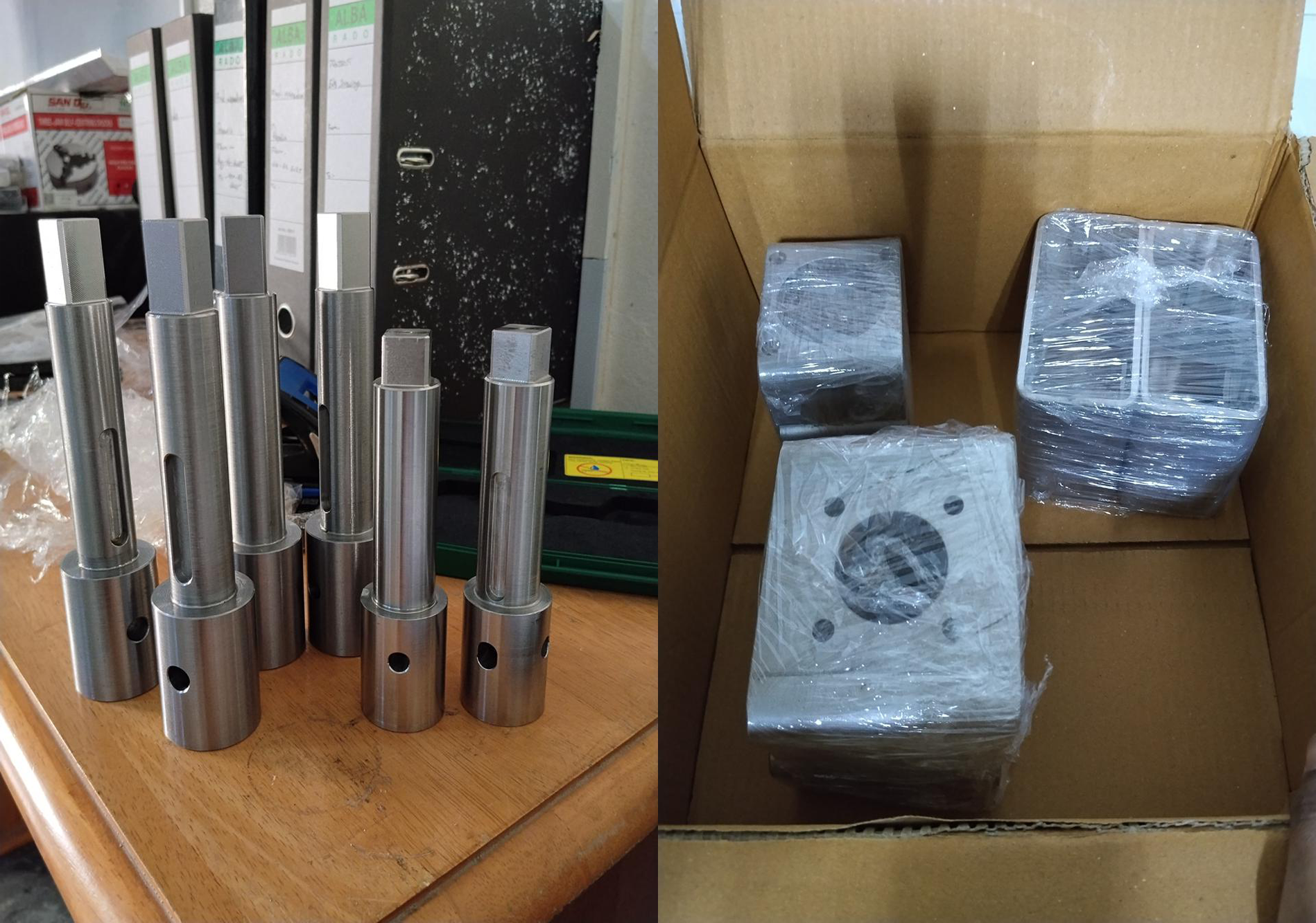
These CNC-machined parts are custom-engineered to precisely match every component, ensuring seamless integration between the valve, manual gearbox, and actuator.
5. Key Takeaway for Vessel Operators
Regardless of the documentation or manufacturing certificates provided, a physical verification of the mechanical alignment between the valve stem and the actuator interface is mandatory prior to final installation.
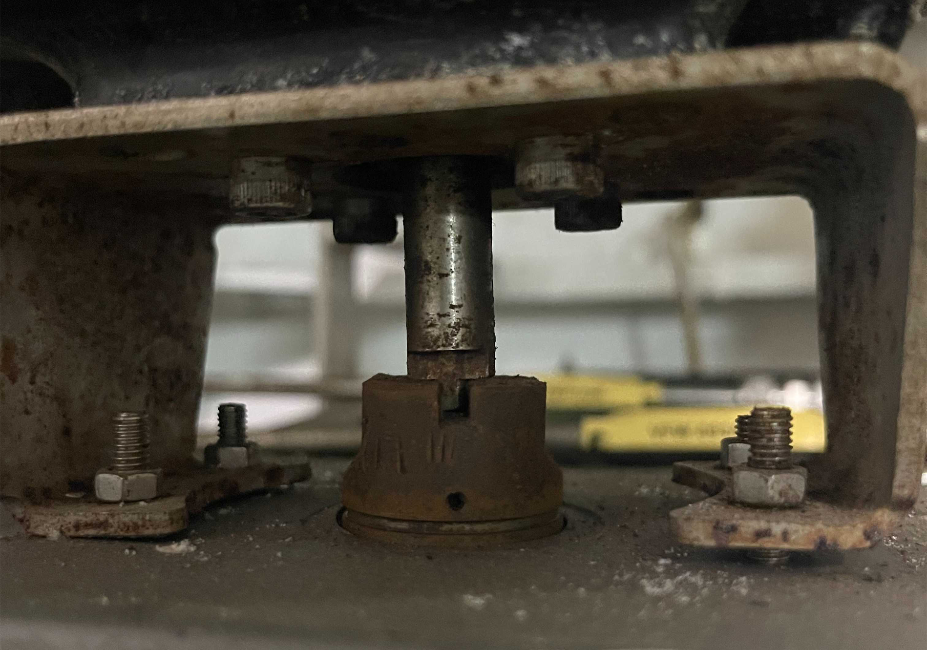
Physical inspection of the legacy assembly reveals a complete geometric mismatch that prevents torque transmission:
- 90-Degree Phase Discrepancy: The valve drive stem and the internal coupling socket are misaligned by exactly 90 degrees. As indicated by the keyway positioning, the driving flats are oriented perpendicularly to the receiving slots, causing the components to bottom out against each other face-to-face instead of interlocking.
- Axial Displacement and Skew: Due to the inability of the profiles to engage, the entire adapter assembly is displaced axially. The lower-right mounting face is lifted and completely unseated from the base flange, inducing a severe angular skew across the drive axis.
Operating a pneumatic actuator against an unengaged, misaligned interface leads to immediate mechanical lock, resulting in sheared keys, structural failure of the adapter, or actuator stall during the initial stroke command.